Last time we made a blinking LED program to run on the ATMega16 board. With a strong conviction that we can now send output hurtling across any pin on any port, we step into our second experiment. Digital input output. The AVR says hello when I say hello to it, because that is how the world works. Not before, nor after. Because we haven’t done any talking yet, the first problem is, how do I break the ice, how do I say hello?
Know that anything inside a digital machine is either a high or a low (or a tri-state). So even if I made a full-fledged interface with a keyboard or some complex gadgetry, the digital machine would still convert it into a sequence of zeros and ones (The machine would do it in that way if I programmed it that way). So, why take that unnecessary detour right now when all I want to do is say hello. We barely know each other? Now if you look into the ATMega16 datasheet at its pin diagram, you’ll find that we have a VCC marked on Pin10. This takes in 5V DC Voltage supply on our board and hence siphoning off a 5V line from this point as a logic one is safe for now (because we don’t have any loading on ports). So, if we connect a 5V line to the input Pin, it counts as a logic 1 and if we ground it, it counts as a 0. What if we don’t connect it at all? We’ll find that out the hard way.
The ATMega16 has 4 ports with 8 programmable pins for each. Most of the pins also have special purposes and also allow the mixed use of the pins as Digital Input/Output pins and Analog input pins. Each Pin has three I/O Memory locations for it in the Port Map Memory – PORTxn, DDRxn and PINxn where 'x' denotes the port name and 'n' denotes the pin number. The PINxn is a read only register and gets the value on that port irrespective of its being Input or Output. DDR is Data Direction Register and sets the direction of data flow on the port. A high value denotes Output. PORTxn is used to set the logic to high or low when using the pin as output and enables or disables the Pull Up circuit when using the pin as input.
Why do we need a pull up resistor? Well, that is pretty much the same reason why some men (and most babies) need suspenders. To hold the pants in place irrespective of the waist size of the person wearing it. If no input is applied on the pin deliberately, we want it to stay at a particular voltage level. When we are using a pull-up resistor we are forcing the input to match up to the high voltage level (pulling it up to Voltage Level High). If we use a pull-down, it will effectively pull the input at pin to Voltage Level low. This is to ensure that there is never a floating pin because a floating pin is susceptible to noise, and that noise can lead to erratic behavior in our setup. A simple tutorial on this is available here.
So, why wait, let’s do it. We will use PORTA for this purpose (it is capricious, you can use any). Its Pin0 will be the INPUT pin and Pin1 will be the output pin. The output will be off by default. Then we’ll endlessly check if some input has been applied on Pin0 and if it is, switch on Pin1. Simple, a hi for a hi.
- Include Header:
#include <avr/io.h>
- Set Data Direction Register for Pin1 of PortA to High, as explained above: Now, there are many ways to do it, but let’s stick with the most basic one. We are going to create a bitmask and apply it on the entire port. Since we want the second pin to be made 1 and leave all others unchanged, we want a bit mask like 0x00000010. ORing this with our PortA will do what we want.
DDRA |= 2; //because 2 is represented as 0x00000010 in binary.
Initially: DDRA = 0x00000000
2=0x0000010;
DDRA | 2 => DDRA = 0x00000010
- Though all ports are usually defaulted to zero, we need not set the pin0 as input. But just to be sure, we will do it.
DDRA &= ~(1<<PA0);
Now: DDRA = 0x00000001
Mask = ~(0x00000010) = 0x11111110;
DDRA & Val => 0x00000010
- Set the Logic Level to low on PortA Pin1.
PORTA &= ~(1<<PA1); //Set Pin 1 to Low
Initially, values at PORTA = 0x00000000
Mask = ~(0x00000010)= 0x11111101
PORTA & Val => 0x00000000
- Now, inside an infinite loop, repeatedly check if the input pin has logic 1.
If (PINA & (1<<PA0)) //If PINA0 is high{PORTA |= (1<<PA1); //Set Pin1 to high}else{PORTA &= ~(1<<PA1); //Set Pin1 to low.}
Let PINA=0x00000000 (Pin0 is low, last bit is 0)
Mask = 0x00000001
PINA & val => 0x00000000 (Not True)
Let PINA= 0x00000001 (Pin0 is high, last bit is 1)
Mask = 0x00000001
PINA & => 0x00000001 (True, turn on Pin1)
This else block is necessary to turn the switch off when the input on Pin0 is removed.
The logic looks well and should work fine. This will work fine (I’ve tested it), but before we compile it, let me shed some light on what I learnt. I made plenty of mistakes here (those are not shown). The major one follows. If you look at the datasheet, it will say that PINA0 means the status on Pin0 of PortA. Well, that is correct theoretically. But inside C language, it is merely a macro with value 0. So, instead of masking the entire Port Status in the if condition, if I wrote if(PINA0) { …} this would never work. Because though I am telling the compiler to access the bit status on the Zeroth Pin, the C compiler has it as a macro and not as a direct Pin status. If you want pin status, you have to write the entire masking statement.
Second, notice that when we set up the Pin0 as input, we did not activate its pull-up circuit. Why, because we don’t want it to be at logic high when there is no input and AVR does not have Pull-Down circuits. This gave me many baffling hours. The code is correct logically, but the behavior of a floating input is often undefined. It is tri-stated, a reference chart is given from the datasheet.
|
DDRxn |
PORTxn |
PUD(in SFIOR) |
I/O |
Pull-Up |
Comment |
|
0 |
0 |
X |
Input |
No |
Tri-State |
|
0 |
1 |
0 |
Input |
Yes |
Pxn will source current if ext. pulled low |
|
0 |
1 |
1 |
Input |
No |
Tri-State |
|
1 |
0 |
X |
Output |
No |
Output-Low (Sink) |
|
1 |
1 |
X |
Output |
No |
Output-High (Source) |
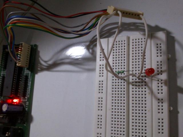
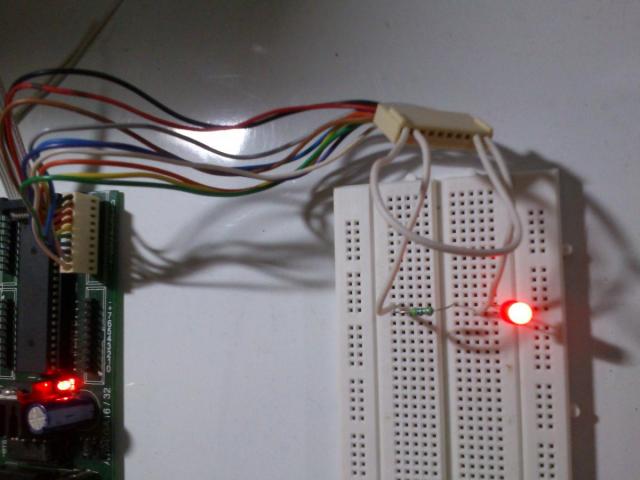
I did not keep that in mind and that spelled trouble. The LED on output pin should not be switched ON when there is no Logic High on input according to what we've written in code. But, I noted that the LED was always ON. When we applied a logic high, the intensity in LED increased. When the voltages across the pins were measured, it showed a value of around 2.3V across the input port and that seemed absurd. Then it clicked... The moment I grounded the Input, the LED turned off. This is what I wanted and this is what was wrong. Shown below are snapshots in three states:
1. No Input: Tri-State (The intensity of light emitted by LED is lesser than that at full Logic 1, something that my mobile cam could not capture well)

2. Zero Input

3. Logic High on Input

Lessons learned? Read the document carefully before implementing.
This spreading out of a bit mask is a calculation that I had trouble making in my head, even though I have done this implicitly many times. But, just to be clear and to etch the concept in my brain, I did it again. For those who have had trouble in creating such bit masks, here is a nice tutorial (though I think this method of spreading out what is happening under the hood gives a clearer picture).
The link to complete source, the Object and Hex file is here